

Our Clock Technology
Clocks are a vital part of digital audio reproduction. Clocks determine the exact timing of the conversion process. Each sample needs to be placed at exactly the correct time to faithfully recreate the original analog sound. Below are examples of how MSB provides attention to every aspect of our purpose-built clocks.
What gives MSB’s audio clocks their unique design?
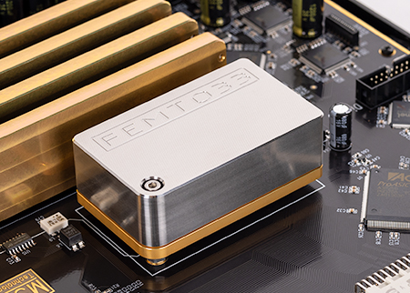
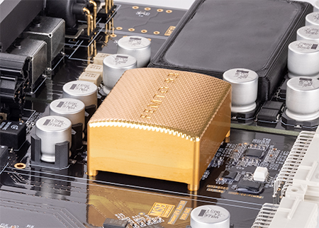
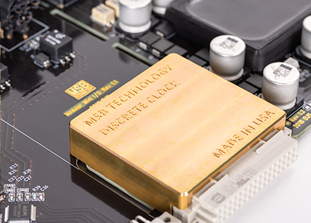
Each of our DACs uses a custom in-house designed and manufactured clock module. Our clocks are uniquely designed for maximum audio conversion quality. Each clock module is made with custom handcrafted parts and is independently calibrated for optimal performance. We developed our first custom handcrafted clock in 2011 and have improved the technology since. Every clock module we make is actually two independent clocks in each module. There’s an independent oscillator for each frequency family. Only one of these circuits is turned on at a time; having the second clock on would add additional unwanted noise. Before the audio playback starts, the DAC determines the base sample rate and selects the correct playback clock. This allows the DAC and the entire system to run off a single native clock at the correct frequency, without the need for conversion by a PLL, SRC, ASRC, or frequency synthesizer.
All of our design builds upon the primary design goal of our clocks having the absolute lowest jitter. Every time we developed a lower jitter clock, we told ourselves there would probably be no additional audible improvement–but we proved ourselves wrong with each iteration. Lowering the jitter audibly improves DAC performance in a linear fashion; there doesn’t seem to be any diminishing returns.
It’s also important to know what happens with the clock after it leaves the oscillators. Jitter is an additive noise. Every time the clock goes through a device jitter is added. This is why you’ll find the clock right next to the DAC modules on the analog side of the circuitry. We treat the clock as an analog component and we maintain the lowest possible jitter in every step between the clock module, right to the point of conversion in the DAC module.
Why is it important for a DAC to have two clocks?
The vast majority of digital audio was recorded within two different frequency families: multiples of 44.1kHz and multiples of 48kHz. The 44.1kHz family includes CD, DSD and many high resolution formats such as 176.4kHz. The 48kHz family includes most sound recorded along with video and many high resolution formats, such as 96kHz and 192kHz audio. But there are differences between these two frequency families. One oscillator–such as 10Mhz or 27MHz–can be converted into the frequencies required to play back both the 44.1kHz and 48kHz families. However, the electrical circuits required are extremely lossy, leading to a large degradation of clock precision. There are various techniques for converting one clock frequency into another. For example, clock synthesizers, PLLs or ASRCs can be used, but they’re all very lossy. The best solution is to have an independent clock oscillator for each frequency family chosen for each playback scenario.
Why clock jitter is more important than accuracy?
An audio clock needs to be as low-noise and low-jitter as possible. The DAC itself recreates the correct signal amplitude, but it’s the clock that recreates the correct signal timing. Jitter is a measure of how precise each clock tick is. If each second is exactly the same length, this indicates low jitter. If some seconds are longer or shorter than others, this indicates high jitter. Clock accuracy is a measure of how close the average second of a clock is to the theoretically perfect second. Audio playback needs super low jitter but not super strict accuracy. If a clock is jittery, each part of a signal is being placed at the wrong time relative to the others, so the sound will be distorted in an unnatural way. However, if a song plays back slightly fast or slow due to the inaccuracy of a clock, it won’t be noticed. Since an extremely low accuracy clock (+-100ppm) will change the length of a one hour recording less than half a second, it’s apparent clock accuracy doesn’t matter much. Most clock technology is designed for communication systems, which need extreme accuracy to keep far flung nets in synchronization. These clocks are not optimized for low jitter at all– just high accuracy. Using ultra-precision communication clocks is not a great solution for audio playback. Digital audio clocks need to be low jitter first and foremost.
Why are external clocks sub-optimal for digital audio?
A clock signal is a fast moving precision electrical signal and is extremely sensitive to added noise or distortion. Each time it’s buffered or transmitted, a portion of its precision is lost. Even if a small amount of noise couples into the clocks, jitter will increase dramatically. It might still be an accurate clock, but accuracy is of little performance benefit to digital audio. A clock sent over an ultra-high quality cable will still increase its jitter considerably. The best solution is to create the lowest jitter clock as close to the DAC as possible.
What is Phase Noise and why does it matter?
Finally, there’s an important note about jitter measurements and comparing different clocks. The published jitter number in pico or femto seconds is a result of conversion calculation from a phase noise measurement. A phase noise measurement is the “whole picture” of how a clock’s frequency changes with time. Jitter is just a single number distillation of a phase noise measurement. Depending on the parameters of this distillation,radically different numbers for jitter can be created. A jitter number depends on a phenomenon called integration bandwidth. If you change the integration bandwidth assumptions for the same high quality oscillator, you can get very different numbers. This makes it difficult to compare jitter specifications from different manufacturers. For example, jitter specifications from 7fs to 300fs can be truthfully published for the same exact oscillator by changing the integration bandwidth. If you want to compare two oscillators apples to apples, you need to know the jitter specification, as well as the data (phase noise) and bandwidth used to calculate the jitter numbers.

